Generic analog components are all accessed via a common set of Python functions.
Hardware
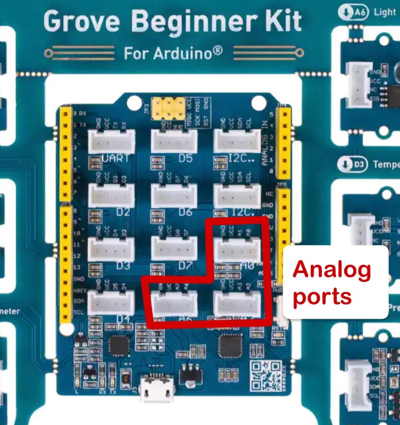
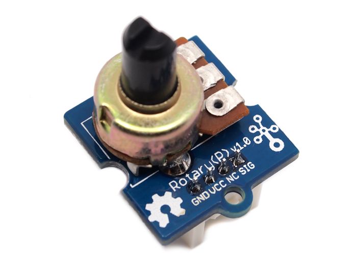
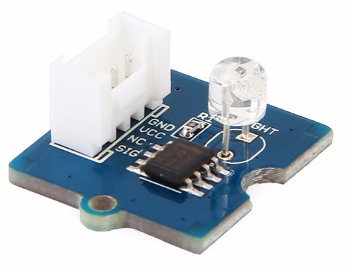
Analog component can include the rotary dial, light sensor, sound sensor or others. Unlike digital components, which are either "on" or "off", analog components can either generate or accept a signal anywhere in a range of values (in our case, anywhere between 0 and 5 Volts). Those included in the Beginner Kit (rotary dial, light sensor, sound sensor) are connected to the analog port specified on the Beginner Kit board; external Grove components can be connected to one of the analog ("A") ports on the Grove shield:
Software
Functions for interacting with analog pins are prefixed with analog.
Initialization
No special initialization is required for interacting with analog components.
Reading from analog pins
To read an analog value from a sensor such as a light sensor or rotary dial,
use the analog_read function provided by our Arduino library:
def analog_read(pin):
    """Read a value from an analog port.

    Parameters:
      pin (int):     Analog pin to read from (e.g., 2 for A2).

    Returns:         Quantized analog value (0–1023).
    """
This will return a value between 0 and 1023, where 0 represents 0 Volts (off) and 1023 represents 5 Volts (on). Intermediate values represent intermediate sensor inputs, e.g., a partially-shaded light sensor or a partially-turned rotary dial.
Writing to analog pins
To write an analog value to an actuator such as a servo,
use the analog_write function provided by our Arduino library:
def analog_write(pin, duty):
    """Write a value to an analog port.

    Parameters:
      pin (int):     Analog pin to write to (e.g., 2 for A2).
      duty (int):    Duty cycle to set (0–255).
    """
Writing to an analog pin is slightly different from reading. Whereas analog sensors produce voltages between 0 and 5 V, which the Arduino interprets as integers between 0 and 1023, writing to an analog pin doesn’t produce a steady voltage between 0 and 5 V. Instead, analog output is simulated: the pin switches between 0 and 5 V, with the duty cycle determining how much time it spends at 0 vs 5 V.